The shield
In order to be able to play with ATtiny devices, you need a programmer. Unlike Arduinos, which have a boot loader using which you program it directly over the USB serial connection, ATtinys don’t have such a direct connection. You need a separate device that can put the ATtiny into programming mode, and send it the code. You can use an Arduino to do that, by using a specific sketch that handles the programming protocol and that passes on the code to the ATtiny it is talking to.
The are many to wire up the Arduino and the AVR device that you want to program. One schematic I found adds 3 status LEDs to the setup, so that you can visually monitor whether the device is being programmed. I modified the schematic to include both an 8 pin socket and a 28 pin socket, so that it can be used to program both ATtinys and ATmegas. I also added a 4th LED that is wired to digital pin 0 on both the ATtiny and the ATmega socked. This can be used to test a chip, by downloading a “blink” sketch to it that pulsates digital pin 0.

I turned this into a “shield” that can be plugged onto an Arduino, to have a semi-permanent programmer at my disposal. The PCB for this looks like this:

Bottom of the PCB

Top of the PCB, with component indications. The red traces symbolise jumper wires.
The finished programmer looks like this:
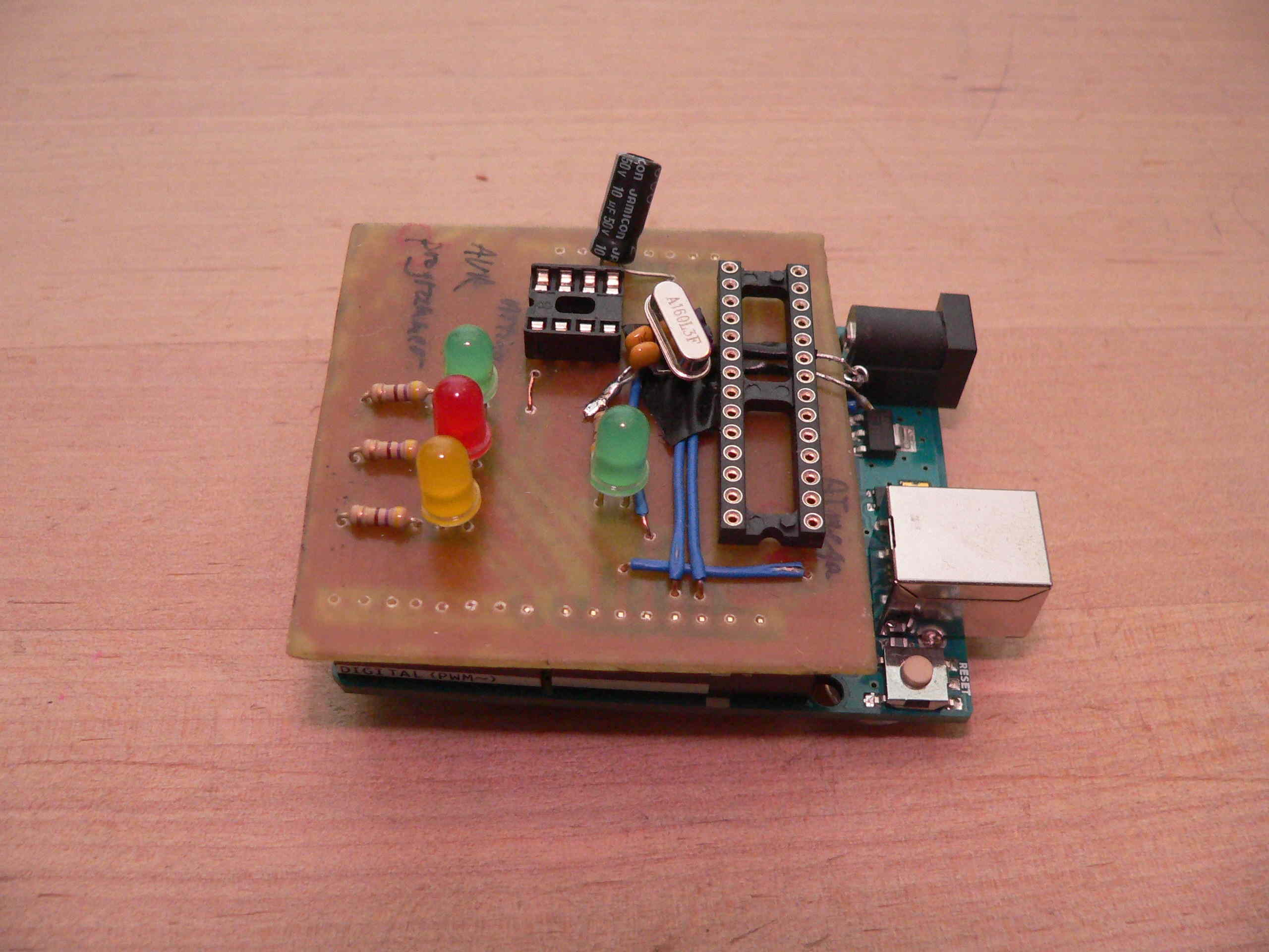
I forgot to put an external crystal on the board for the ATmega socket, so I wired this in place after the fact; it’s ugly, but it works…
Software
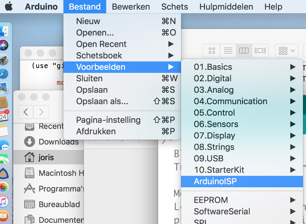
The Arduino that controls the shield should be flashed with the “ArduinoISP” sketch. You’ll find this in the File > Examples menu:
The Arduino IDE
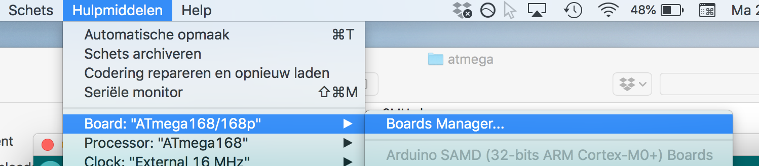
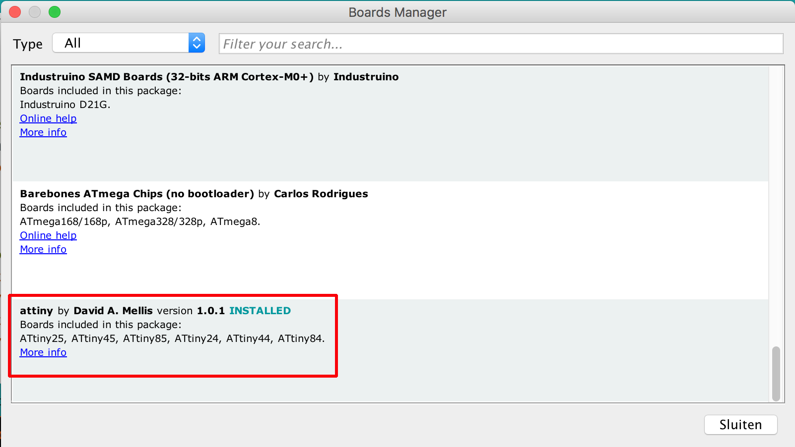
You have to update your Arduino IDE to be aware of the ATtiny / ATmega programmer. In order to program ATtinys, install the “attiny” definitions in your Arduino IDE to make (reference 2) using the Board Manager:
For ATmega328s, the “Barebones ATmega chips (no bootloader)” definitions seem to work OK:

For ATmega168s, I’ve had to modify the definitions from the “Barebones” package a bit: in the boards.txt file, I had to change
atmega168.menu.clock.internal1.bootloader.extended_fuses=0xf9
to
atmega168.menu.clock.internal1.bootloader.extended_fuses=0x00
for all definitions (internal1, internal8, external8,…), in order for avrdude to stop complaining about a verification mismatch. I’m not sure if this message was specific to my particular set of ATmega168s.
I also added
atmega168.menu.cpu.atmega168.bootloader.file=atmega/ATmegaBOOT_168_diecimila.hex
to the definitions, so an Arduino bootloader can be programmed in the ATmega168. This should allow them to be used on an Arduino board.
When programming, you select the MCU type (ATtiny, ATmega168, ATmega328) from the Tools > Board menu, select your specific device, and the desired clock frequency. Make sure to select “Arduino as ISP” as the programmer.
Results
The shield can be used to program ATtinys (45 / 85) directly.
For ATmega168s and 1Tmega328s, I’ve been able to program both Arduino bootloaders and sketches.
If you want to test a chip before burning your sketch to it, you can program the “Blink” sketch first (from the basic examples). If you replace LED_BUILTIN with PD0, this sketch will flash the green led on the shield if it the upload succeeds.
References
- Using an Arduino as an AVR ISP
- How to install ATtiny definitions in Arduino IDE
- ATmega definitions for Arduino IDE
- Apple-style LED pulsing using a $1.30 MCU ATtiny C program that I used to test the programmer